Megawatt Compute Racks!
Table of Contents
I’ve designed a lot of racks. Most of them land somewhere between 10 and 15 kW. That’s the enterprise baseline, the design point that most of the world’s installed data center capacity is built around. Standard power distribution, off-the-shelf PDUs, hot aisle/cold aisle airflow. The physics are solved, the playbook is 30 years old, and nothing about it is surprising.
The racks going into AI facilities right now are a different species entirely. The ones being installed today are in the 80 to 100 kW range. The ones coming next are over a megawatt. Each step breaks assumptions from the one before it.
Glossary — acronyms and jargon used in this post
AC / DC — Alternating current / direct current. AC is what comes from the wall; DC is what processors actually run on. Every server has a power supply that converts AC to DC internally. The efficiency push in modern datacenters is about doing that conversion once, at high voltage, rather than repeatedly at lower voltages inside each server.
Aisle containment (hot aisle / cold aisle) — A layout convention where racks face alternating directions so that cold air intakes face a “cold aisle” and hot exhaust faces a “hot aisle.” Containment means physically enclosing one or both aisles with panels and doors to prevent cold and hot air from mixing, which makes cooling far more efficient.
AllReduce — A collective communication operation used in distributed GPU training where each GPU sends its gradient updates to all others and receives theirs back simultaneously. It’s the most bandwidth-intensive operation in large model training, and the reason interconnect bandwidth between GPUs is as important as raw compute.
Ampacity — The maximum current a conductor (wire, bus bar) can carry continuously without overheating. Higher ampacity requires either thicker conductors or higher voltage to carry the same power.
Blind-mate connector — A connector designed to make contact automatically as a component slides into position, without manual alignment or plugging. Used in high-density datacenter systems so a server tray makes both electrical and liquid cooling connections in a single insertion motion.
Bus bar — A solid copper or aluminum conductor that distributes power through a rack or row. Higher ampacity than wire bundles; used in datacenter power distribution because it handles high currents more efficiently than discrete cables.
Busway — An overhead or underfloor power distribution track (think: a giant extension cord rail) that runs the length of a server row and provides tap-off points for each rack. Replaces individual conduit runs at high rack densities where per-rack wiring becomes impractical.
CDU (Coolant Distribution Unit) — The rack-level or row-level appliance that circulates chilled water through a liquid-cooled system. It typically includes pumps, a heat exchanger that connects to the building’s facility water loop, and flow controls. Think of it as the “radiator unit” for a liquid-cooled rack.
CFM (Cubic Feet per Minute) — A measure of airflow volume. Used to quantify how much air needs to move through a rack for air cooling. At 100 kW densities, the CFM requirements become loud, physically challenging, and expensive.
Cold plate — A metal block (usually copper) bolted directly onto a GPU or CPU that has internal channels carrying coolant. Transfers heat from the chip directly into the liquid rather than into the surrounding air.
CRAC (Computer Room Air Conditioner) — The dedicated precision air conditioning units used in datacenters. Unlike home AC, they’re designed for high-sensible-heat loads (mostly heat, little humidity control) and run continuously. At 100 kW rack densities, you typically need one every few rows rather than around the perimeter.
DLC (Direct Liquid Cooling) — A cooling approach where liquid-carrying cold plates are attached directly to heat-generating components (GPUs, CPUs). The heat goes straight into the coolant rather than first into the air. Required at megawatt densities where air physically cannot carry enough heat.
GaN (Gallium Nitride) — A wide-bandgap semiconductor used in high-frequency power conversion. More efficient than silicon at high switching speeds; used in DC-DC conversion stages in datacenter power supplies and increasingly in consumer chargers.
GOES (Grain-Oriented Electrical Steel) — A specialty steel used in transformer cores. The grain alignment is optimized to reduce magnetic losses. There’s limited global production capacity, and both AI datacenter buildout and renewable energy interconnection are competing for it.
HVDC (High-Voltage DC) — A power distribution approach that distributes DC power at high voltage (48V, 400V, or 800V) through a datacenter rather than distributing AC and converting it at each server. Eliminates conversion stages and reduces energy losses.
IGBT (Insulated Gate Bipolar Transistor) — A power semiconductor switch used in UPS systems, solar inverters, and motor drives. Being progressively replaced by SiC in high-performance applications due to SiC’s better efficiency at high voltages and temperatures.
LPM (Liters per Minute) — The flow rate of coolant through a liquid cooling loop. At 1.2 LPM/kW (the industry rule of thumb for direct liquid cooling), an 85 kW rack requires around 102 LPM.
NVLink — NVIDIA’s proprietary high-bandwidth interconnect for GPU-to-GPU communication within a rack or system. Much faster than PCIe or Ethernet; allows multiple GPUs to act as a single unified compute resource.
OCP (Open Compute Project) — A Meta-founded industry consortium that publishes open hardware specifications for datacenter equipment: racks, power distribution, servers, networking. ORV3 (Open Rack Version 3) is their current rack standard; it defines bus bar voltage, connector specs, and physical dimensions.
ODM (Original Design Manufacturer) — Companies like Wiwynn, Quanta, and Supermicro that design and manufacture servers sold under another brand or sold directly to hyperscalers. The AI rack market is largely built on ODM hardware.
OpEx — Operating expenditure; ongoing costs like power, cooling, and staffing. Contrasted with CapEx (capital expenditure), which is the upfront cost of building or buying infrastructure.
PDU (Power Distribution Unit) — The rack-level power strip, essentially, but engineered for datacenter loads. Provides individual branch circuits to each server with metering and protection. At 100 kW densities they’re large, heavy, and custom-spec’d rather than off-the-shelf.
PUE (Power Usage Effectiveness) — The ratio of total facility power to IT equipment power. A PUE of 1.0 is theoretically perfect (all power goes to compute). 1.2 means 20% overhead for cooling and lighting. Lower is better; modern liquid-cooled facilities approach 1.1 to 1.2.
Raised floor — A floor system with removable tiles sitting above the structural slab, creating a plenum underneath for cabling and air distribution. Standard in enterprise datacenters; the underfloor space distributes cold air up through perforated tiles to server inlets.
RDHx / Rear-Door Heat Exchanger — A heat exchanger that replaces the rear door of a standard rack and captures heat from the rack’s exhaust airflow by running chilled water through a finned coil. A hybrid approach: rack fans still run, but the liquid loop captures a large portion of the heat before it reaches the room.
SiC (Silicon Carbide) — A wide-bandgap semiconductor with better high-voltage and high-temperature performance than silicon. Used in EV traction inverters, solar inverters, and increasingly in datacenter power conversion. The same 1,200V SiC MOSFET goes into both 800V EV drivetrains and 800VDC datacenter rectifiers.
Switchgear — High-voltage electrical equipment that controls, protects, and isolates power distribution circuits. The large metal cabinets you see at the entry point of a facility’s electrical system. Lead times for datacenter-grade switchgear have extended significantly as AI buildout demand accelerates.
UPS (Uninterruptible Power Supply) — A battery-backed power system that provides continuous power during utility outages or fluctuations. Datacenter UPS systems use a “double-conversion” topology where all power passes through the battery inverter continuously, giving true zero-transfer-time protection at the cost of some efficiency.
42U — A rack size designation where “U” is a rack unit (1.75 inches). A 42U rack is 73.5 inches tall, the most common standard height. Higher-density AI racks may run 48U or more.
A standard data center rack is roughly 42U to 48U tall (about 7 feet), 24 inches wide, and 36 to 48 inches deep. Call it 18 to 24 cubic feet of usable volume. That physical envelope is the constant across everything that follows. A 10 kW enterprise rack, a 100 kW AI rack, and a 1 MW hyperscale system all occupy roughly the same floor footprint. The density jump is what changes everything else.
The baseline: what 10–15 kW per rack looks like
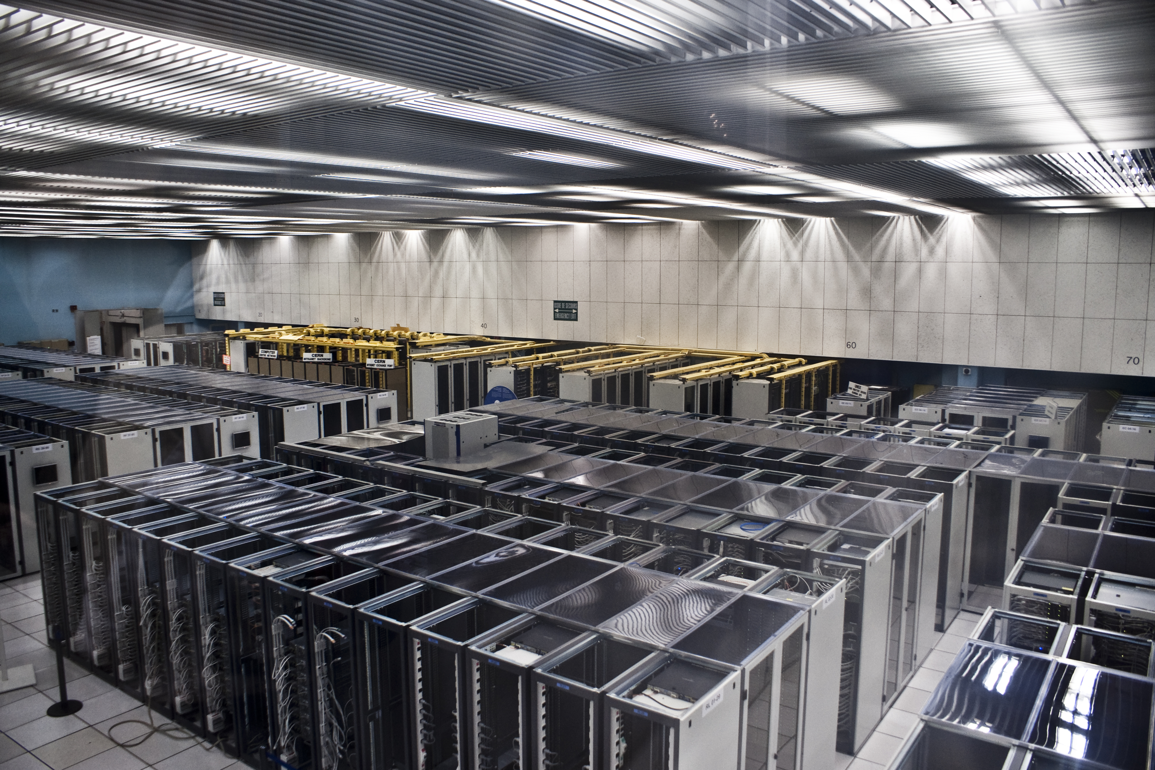
The CERN data centre: rows of enclosed racks with hot/cold aisle containment, CRAC units along the back wall, raised floor, overhead cable trays. Classic enterprise design, refined over 30 years. Photo: Florian Hirzinger, CC BY-SA 3.0
A typical rack in this range has 20 to 40 servers, each pulling 300 to 500 watts at load. Three-phase AC, maybe 208V or 480V. PDUs are catalog items. Your biggest concern is cable management.
Cooling is straightforward: hot aisle/cold aisle containment, CRAC units pushing conditioned air, done. Air has enough thermal capacity to carry the heat load out of the rack before anything catches fire. Enterprise data centers are typically designed for 150 to 200 watts per square foot of raised floor, and these racks fit comfortably inside that.
This is the installed base (something like 90% of rack capacity in the world right now). The buildings that house it were designed for it. Thousands of these facilities exist and the design has been refined over 30 years.
The middle tier: 80–100 kW racks being deployed today
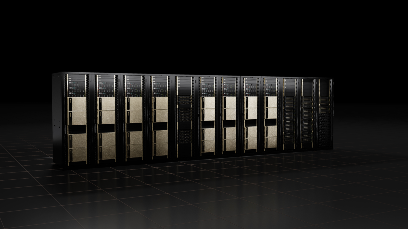
NVIDIA DGX SuperPOD — a cluster of DGX H100 racks. Each populated rack runs 40 to 50 kW; a full SuperPOD row approaches 100 kW per rack footprint. Image: NVIDIA
The first wave of purpose-built AI data centers isn’t running megawatt racks. It’s running GPU clusters in the 80 to 100 kW per rack range. Think DGX H100 clusters, or dense A100/H100 configurations from ODMs like Wiwynn, Quanta, or Supermicro. This is what’s actually getting installed at scale right now, and it already breaks the enterprise playbook in several important ways.
At 80 to 100 kW, air cooling is still technically possible but you’re working against physics rather than with it. The airflow volumes required are substantial: roughly 2,000 to 3,000 CFM through a single rack, which means high-velocity fans, significant acoustic load, and real structural air management. Hot aisle containment stops being optional and becomes mandatory. Cold aisle containment and blanking panels have to be perfect; any bypass airflow means hot spots. A lot of facilities running these densities are running at CRAC unit limits, with CRACs located every few rows rather than around the perimeter.
The power delivery changes significantly too. At 100 kW per rack you’re looking at 400 to 500 amps at 208V three-phase, which means you’re no longer running standard 30A or 60A branch circuits to a PDU. You need high-amperage three-phase feeds, often delivered via overhead busway (a dedicated power track running the length of the row) rather than individual conduit runs. The PDUs themselves are large, heavy, and rated for continuous 80%+ of their maximum load. Branch circuit protection, cord sizing, and PDU tap-off points all have to be engineered specifically for the load. This isn’t a catalog selection anymore.
Hyperscalers building for this tier are also pushing past 48V DC distribution and moving to 400VDC and 800VDC architectures, centralizing the AC-to-DC rectification closer to the utility feed and distributing high-voltage DC directly to the rack row. The efficiency gains at 100 kW density are real enough that Meta, Google, and Microsoft are all deploying medium-voltage distribution (some running as high as 13.8 kV) before stepping down to rack-level DC. Delta’s 800VDC “AI Power Cube” (co-developed with NVIDIA) is targeting 1.1 MW-scale racks, but the same architecture is relevant even at 100 kW because it eliminates conversion stages that compound into real money at this density.
The buildings designed for this tier look noticeably different from enterprise data centers. Power density per square foot goes from the 150 to 200W/sqft enterprise standard up to 500 to 800W/sqft for a dense GPU row. That changes transformer sizing, switchgear ratings, UPS topology, and generator capacity significantly. Floor loading is a separate hard constraint: racks with liquid cooling hardware at this density can weigh 2,000 to 3,000 pounds, and if you’re running a coolant distribution unit (CDU) per row, a fully flooded unit alone can weigh around 3 tons, so you need slab capacity around 800 kg/m² rather than the typical raised-floor spec. You also need extended rack depth (standard 42-inch racks won’t fit current NVIDIA HGX servers), and those deeper racks affect aisle spacing and the whole floor layout.
On the cooling side, 100 kW is where two distinct approaches are both in active use and worth understanding separately.
The first is rear-door heat exchangers. A rear-door HX (RDHx) replaces the rack’s back door with a chilled-water coil that the rack’s own fans blow exhaust air through. The liquid captures heat from the airstream before it reaches the room, but air is still the medium moving heat away from the chips. The fans keep running, and you still need hot/cold aisle management. Latest-generation units like OptiCool’s 120 kW RDHx can now absorb close to the full heat load of a 100 kW rack, up from the 40 to 70% capture typical of earlier units. A common 2025 deployment pattern runs about 70% liquid capture via RDHx with the remaining 30% handled by conventional room cooling. This approach works without redesigning the facility cooling loop from scratch, which is why it’s popular as a retrofit and for facilities not quite ready to commit to full direct liquid cooling.
The second approach is direct liquid cooling (DLC), where coolant runs through cold plates bolted directly onto the GPUs and CPUs. No air involved in moving heat away from the chips at all. Heat goes straight into the coolant. DLC is more efficient and handles higher densities, but it requires CDUs, supply and return manifold plumbing, and leak detection throughout. The industry sizing rule for a DLC loop is 1.2 liters per minute per kilowatt at 45°C inlet temperature: an 85 kW rack needs a CDU and manifold supporting roughly 102 LPM of flow. That’s not exotic hardware, but it has to be deliberately designed in rather than bolted on after the fact.
At 100 kW, both approaches are viable. The choice comes down to how the facility was built and what the next GPU generation will demand.
The critical point is that 100 kW racks are demanding but solvable within a purpose-built or heavily upgraded facility. Building new infrastructure to this spec costs somewhere between $200K and $300K per rack in facility-side capital (not counting the compute itself). That’s a real number. Retrofitting an existing facility up to 40 kW density is cheaper, around $50K to $100K per rack, but leaves headroom on the table when the next GPU generation arrives. The challenges are well understood, the vendor ecosystem is mature, and there’s enough operational experience to draw from. None of it requires fundamentally new infrastructure categories. It just requires actually building the right infrastructure rather than adapting what’s already there.
What it does require is supply chain access that’s getting harder to take for granted, because a lot of the components that make 100 kW infrastructure work are the same ones going into utility-scale solar farms by the thousands.
The most acute overlap is in transformers. A 100 kW GPU row drawing several megawatts across a facility hall requires large medium-voltage transformers to step utility power down to distribution voltage. Those same transformer types are going into solar interconnection projects in massive numbers: over 90% of new electric generating capacity installed globally in 2025 was solar and wind, and every one of those projects needs medium-voltage step-up transformers to get power onto the grid. Large power transformers now take two to three years to procure in some cases, versus weeks before 2020. The cores of those transformers require grain-oriented electrical steel (GOES), which in the US is produced by essentially one domestic mill (Cleveland-Cliffs). Hyperscalers have been documented outbidding utility grid suppliers for transformer allocations. That’s not a supply chain abstraction. That’s a literal bidding war between AI infrastructure buildout and the power grid that everyone depends on.
The UPS systems at 100 kW facilities have the same problem at the semiconductor level. Double-conversion UPS units (which virtually all purpose-built AI facilities use, since they can’t tolerate even a millisecond of power interruption during GPU training runs) rely on IGBTs and increasingly SiC MOSFETs for the conversion stages. Those devices are in the same demand pool as solar inverter switching components. A 650V GaN switch or a 1,200V SiC MOSFET doesn’t know if it’s going into a solar microinverter, a UPS module, or a datacenter PDU. The fabs don’t care either. Renesas, for example, is now explicitly marketing a single bidirectional 650V GaN device for both solar inverter and AI datacenter applications simultaneously. That’s convenient for the chip vendor and a scheduling problem for anyone trying to place a large order during a tight quarter.
The copper situation compounds everything at this tier too. Microsoft’s 80 MW Chicago facility used roughly 2,100 tonnes of copper across on-site and near-site power connections (about 26 tonnes per megawatt). Scale that to a 100-rack GPU hall at 10 MW of IT load and you’re sourcing 260 tonnes of copper just for the power infrastructure, before you run any cable to the racks themselves. That copper is competing with the solar farms and grid storage projects being built at unprecedented rates to supply the power those same facilities need. It is genuinely circular: the AI buildout is driving power demand that requires renewable buildout, and both the AI buildout and the renewable buildout are competing for the same copper, transformers, and power semiconductors to do it.
The new world: 1+ MW in the same box
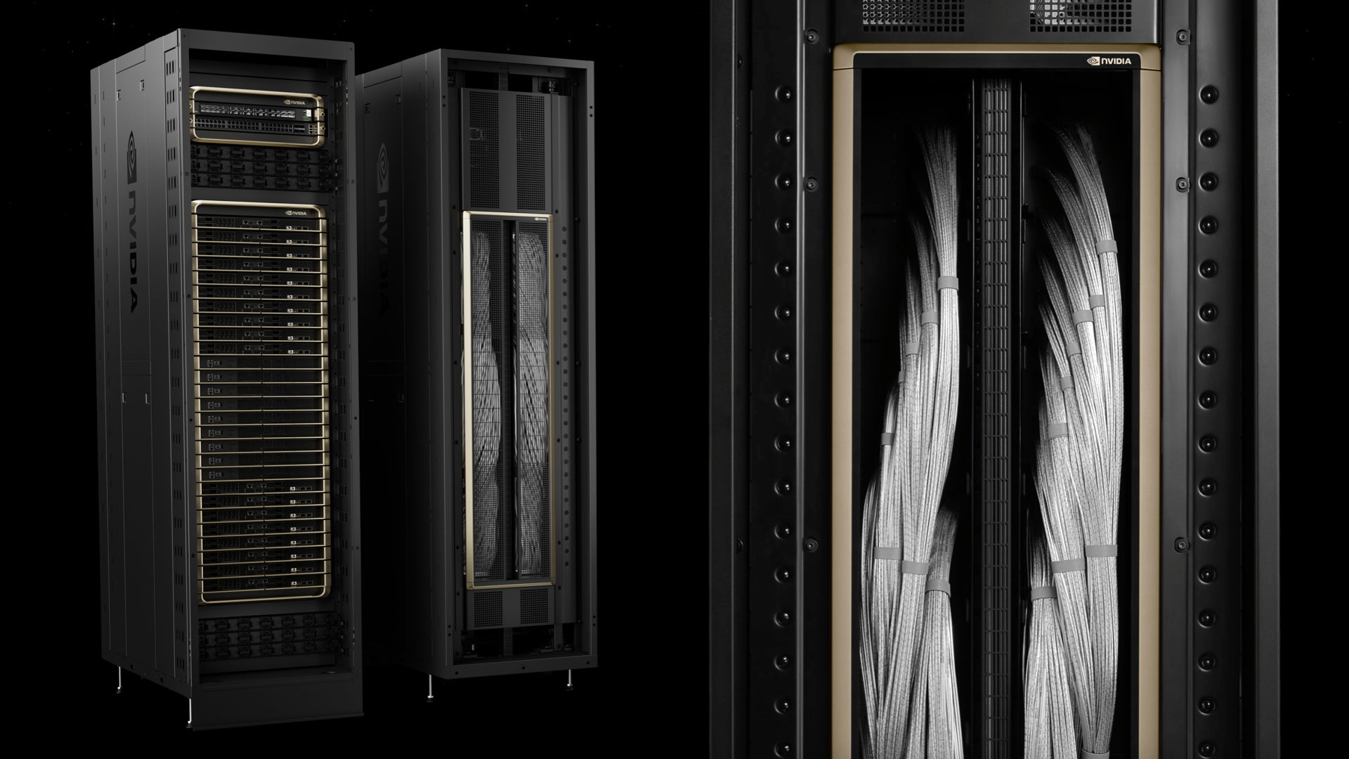
The NVIDIA GB200 NVL72 — 72 Blackwell GPUs, 18 compute trays, 9 switch trays, direct liquid cooling throughout. Over a megawatt at peak load. Image: NVIDIA
The NVL72 (NVIDIA’s GB200 rack-scale system) fits in roughly the same floor footprint as all of the above. Same basic rack envelope. And it draws over a megawatt. That’s not a typo. One megawatt, in a box the size of a large refrigerator cabinet.
The physical layout of the NVL72 is worth understanding because it’s nothing like a conventional rack. Inside you have 18 liquid-cooled compute trays and 9 switch trays, all in 1U form factor, plus 4 NVLink cartridges mounted vertically at the rear. Those 4 cartridges alone contain over 5,000 active copper cables, the interconnect fabric that lets all 72 GPUs talk to each other as a single unified compute domain. Each GPU gets 1.8 TB/s of NVLink bandwidth, which is 36x faster than 400 Gbps Ethernet and about 2x faster than the previous H200 generation (which topped out at 900 GB/s per GPU). The aggregate AllReduce bandwidth across all 72 GPUs is 260 TB/s. That number exists because of those 5,000 copper cables crammed into the rear of the rack.
To put the compute density in physical terms: 1 MW sustained is enough to power somewhere around 800 to 900 average American homes. Coming out of a box that fits in a large office.
NVIDIA contributed the NVL72’s rack, compute tray, and switch tray designs to the Open Compute Project in late 2024, which means the full mechanical and electrical specs are now public. A few things in those specs are worth calling out because they show just how much had to be rethought from first principles.
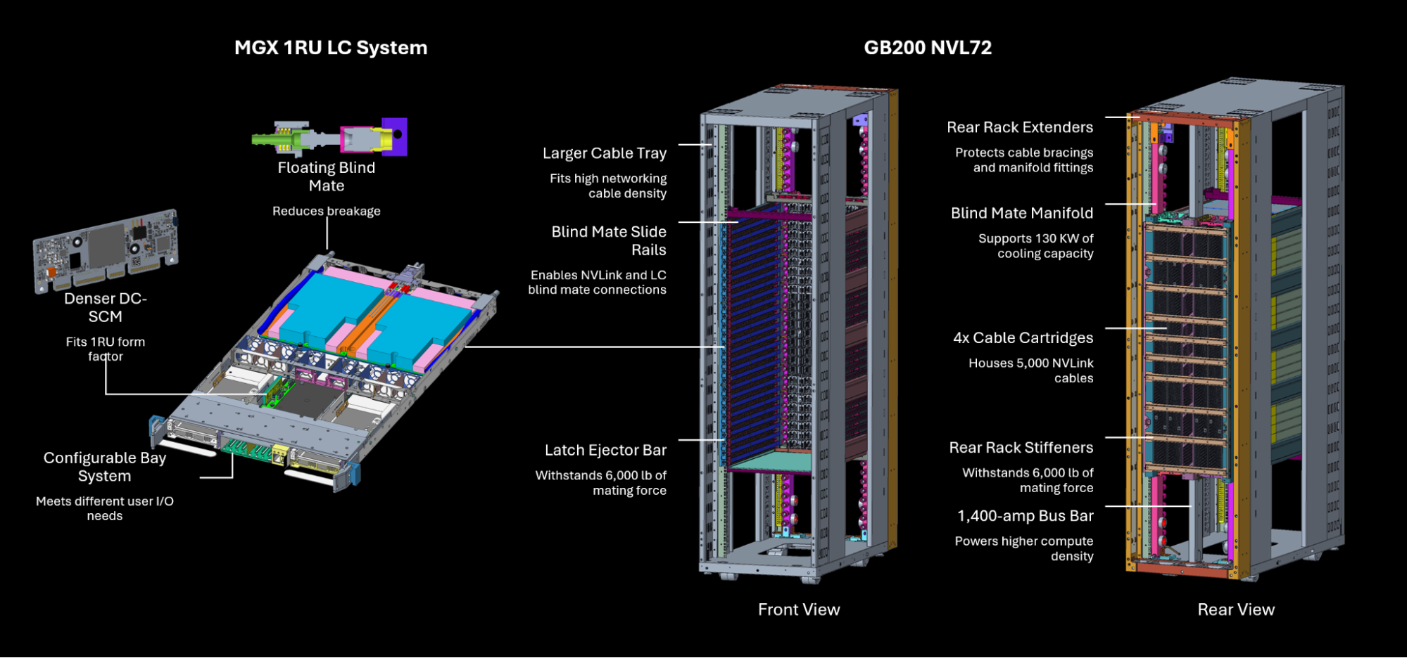
The rack frame has over 100 lbs of steel reinforcements to handle 6,000 lbs of mating force as trays blind-mate into position. The bus bar carries 1,400 amps (double the existing ORV3 standard), same width as before but with a deeper profile for the increased ampacity. The cooling connections use a floating blind-mate liquid cooling manifold: each tray makes its coolant connection automatically as it slides in, the same mechanical motion that makes the electrical connection. No separate plumbing step, no hose connections. The tray goes in, everything connects.
That’s a 7 to 10x jump over the 100 kW racks being deployed today, and 70 to 100x over the enterprise baseline, all in the same floor footprint. And unlike the move from 15 kW to 100 kW (demanding but solvable), the jump to 1 MW broke categories. The existing OCP standards didn’t have answers. NVIDIA had to write new ones.
Power delivery: why you can’t just plug it in
Standard AC power delivery has a dirty secret: every conversion step wastes energy. Electricity comes in from the utility, goes through a transformer, hits a UPS, gets distributed through PDUs, and finally runs through server power supply units that convert it again to DC on the board. Each of those steps is 94 to 97% efficient. Cascade four or five of them and you’ve lost 15 to 25% of your input power to heat before a single computation runs.
At 10 kW per rack, this is annoying but manageable. At 100 kW, it’s a real cost that starts showing up in facility OpEx. At 1 MW, it’s a crisis.
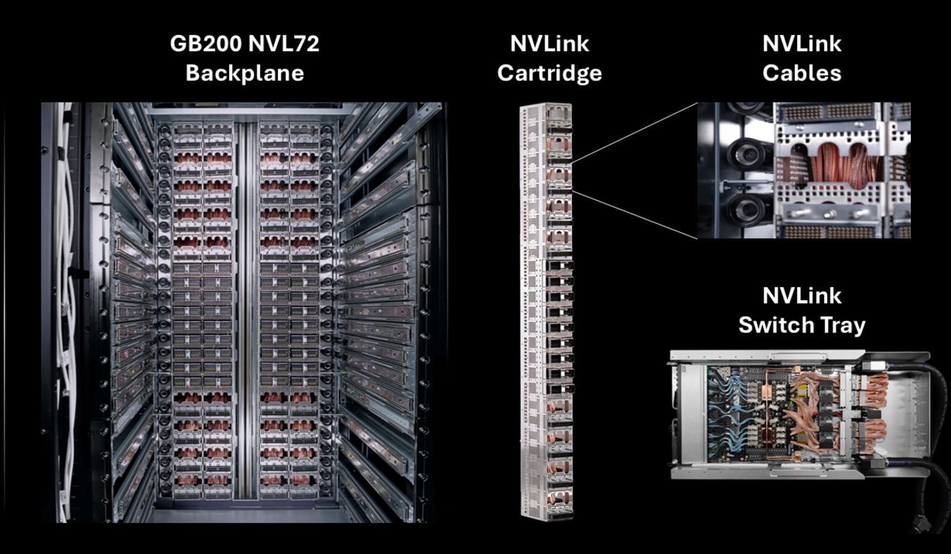
Key highlights from NVIDIA’s GB200 NVL72 OCP submission: new bus bar spec, floating blind-mate cooling manifold, reinforced rack frame. Image: NVIDIA
High-voltage DC delivery eliminates one to two of those conversion stages. The OCP ORV3 standard uses a 48V DC bus bar delivered via blind-mate connector: the rack slides in and makes contact. No cord management, no intermediate conversion, direct DC to the server boards. Some hyperscale deployments push this further to 400V HVDC, eliminating another stage. The NVL72’s enhanced bus bar spec (1,400 amps, as mentioned above) is now part of NVIDIA’s OCP contribution, available to the industry rather than kept proprietary.
The difference between 85% end-to-end efficiency and 95% efficiency is 100 kW of waste heat per megawatt rack. A hundred kilowatts that you’re paying for, generating heat from, and then paying again to cool. That “paying again to cool” part is real and it compounds the loss. Modern liquid-cooled facilities run a PUE around 1.2 to 1.3, meaning roughly 0.2 to 0.3 kW of cooling energy is consumed for every kW of heat the facility has to reject. Apply that to the waste heat alone (the heat that never needed to exist in the first place) and the cooling overhead adds another 25% or so on top of the direct conversion loss cost.
At 1,000 racks (a medium-sized hyperscale hall), the annual cost difference between efficient and inefficient power delivery, counting both the losses and the cost to cool those losses, is somewhere between $130 and $175 million per year. That’s the business case for a 9-figure investment in HVDC infrastructure. The math isn’t subtle.
Here’s a rough comparison across delivery methods for a 1 MW rack, at $0.065/kWh with a 1.25 cooling overhead factor applied to waste heat:
| Power delivery | Efficiency | Loss (kW) | Annual power cost of losses | Annual cooling cost of losses | Total annual waste cost |
|---|---|---|---|---|---|
| Single phase 120V AC | 80 to 82% | 180 to 200 | $100K to $115K | $25K to $29K | $125K to $144K |
| Three phase 208V/480V AC | 88 to 91% | 90 to 120 | $51K to $70K | $13K to $18K | $64K to $88K |
| 48V HVDC (OCP ORV3) | 94 to 96% | 40 to 60 | $23K to $35K | $6K to $9K | $29K to $44K |
The gap between single-phase AC and HVDC, fully loaded, is roughly $96K to $115K per rack per year in pure waste: power you bought, converted to heat you didn’t want, and then spent more money to remove. These numbers are why you see hyperscalers spending billions on power infrastructure before they spend anything on compute.
Cooling: air physically cannot do this job
At 80 to 100 kW, air cooling is already working hard. You’re managing it with rear-door HXs, tight containment, and purpose-built facilities, but the physics are still on your side if you’re disciplined. At 1 MW, you’ve left the realm of “air cooling is expensive” and entered “air cooling is physically impossible in any meaningful sense.” I don’t mean difficult. I mean the airflow velocities required to move enough heat would damage components and make the room uninhabitable.
Here’s the physics. Air has a specific heat capacity of about 1 kJ/kg·°C. Water has about 4.18 kJ/kg·°C. But density matters too: water is about 830 times denser than air at standard conditions. So water carries roughly 3,400 times as much heat per unit volume as air. To remove 1 MW of heat with air at the temperature deltas you can realistically achieve in a data center (maybe 15 to 20°C rise across a rack), you’d need airflow rates that generate serious acoustic problems and create structural forces on lightweight components.
Direct liquid cooling (DLC) is the answer. Coolant flows through cold plates physically attached to GPUs, CPUs, and memory modules. The coolant absorbs heat at the source, carries it to a coolant distribution unit (CDU), and gets rejected to the facility cooling loop. With water as the coolant, you can pull 1 MW out of a rack with a flow rate measured in tens of liters per minute. Manageable with standard chilled water infrastructure, as long as that infrastructure was designed for it.
Cold plates themselves are also getting smarter. The standard approach runs parallel channels in a rectilinear grid across the chip surface, distributing coolant uniformly regardless of where the heat is actually being generated. Modern GPUs aren’t thermally uniform. There are intense hotspots at compute cores and memory interfaces sitting next to relatively cool regions, and a thermally blind cold plate treats all of it the same way. A Swiss EPFL spinout called Corintis is attacking this directly with microfluidic chip-scale cooling: channels roughly 100 microns in diameter (about the width of a human hair) etched into or just above the silicon die, with AI-optimized topologies that route more flow to hotspots and less to cool regions. Microsoft tested an early version on production server hardware and reported 3x better heat removal than advanced cold plates, a 65% reduction in GPU peak temperature, and a 55% drop in pressure compared to a parallel-channel baseline. The next generation goes further, embedding the channels directly in the chip die and co-designing the thermal structure alongside the electronics. I’ve got a full writeup on Corintis in the research section if you want the technical detail. The point here is that cold plates aren’t standing still. The ceiling on what DLC can do at the chip level keeps rising.
Rear-door heat exchangers (a useful stopgap for medium-density racks) get you into the 30 to 50 kW range without touching facility cooling loops. At 1 MW, they’re a footnote.
The facility requirements for DLC at megawatt density are not trivial. You need dedicated CDUs for each rack or row, supply and return manifold piping, leak detection at every connection point (a leak in a 1 MW liquid-cooled rack is a very bad day), and secondary containment for the coolant loop. NVIDIA’s reference architecture for a 7 MW GB200 NVL72 cluster (developed with Vertiv) shows what this looks like at scale: a purpose-built liquid-cooled floor plan where every element, from CDU placement to power distribution topology, is designed around the rack rather than adapted from a conventional air-cooled facility. That reference architecture reportedly cuts deployment time by up to 50% compared to custom-designed approaches, which says something about how standardized this problem is becoming even at megawatt densities.
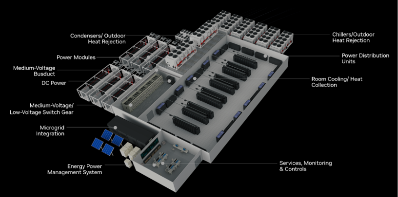
Reference floor plan for a 7 MW GB200 NVL72 cluster, developed by NVIDIA and Vertiv. Every element is designed around the rack’s liquid cooling and HVDC requirements. Image: NVIDIA
This is a ground-up design requirement, and increasingly one with published reference architectures and OCP-standardized components rather than a bespoke engineering problem every time.
What it actually costs to run a 1 MW rack for a year
Let’s put numbers on the full picture. One megawatt of IT load, operating 24/7/365:
- Raw power cost: 1 MW × 8,760 hours × $0.065/kWh = **$569,400 per year**
- Apply a PUE (Power Usage Effectiveness) of 1.2, which is realistic for a modern liquid-cooled facility: total facility load is 1.2 MW
- Total facility power cost: $683,000 per year per rack
That’s before amortizing the cost of the rack itself (the NVL72 is reportedly in the $3 to $4M range per system, before networking), the facility infrastructure, or the power delivery and cooling buildout.
Scale to 1,000 racks and you’re looking at roughly $683M per year in power costs alone. A mid-sized hyperscale AI hall. The infrastructure to support those racks (power substations, cooling towers, HVDC distribution, DLC manifolds) runs another $1 to $2 billion in capital. The compute itself is additional.
This is why the conversation in data center infrastructure has shifted so completely in the last two years. The decisions about PUE targets, power delivery topology, and cooling architecture are not engineering preferences. They’re P&L items. The difference between a 1.4 PUE facility and a 1.2 PUE facility, at this scale, is $136M per year in wasted power costs for that same 1,000-rack hall. Every tenth of a PUE point is worth fighting for.
The supply chain you didn’t expect: this stuff competes with electric cars
Here’s something that doesn’t come up enough in datacenter conversations: a meaningful chunk of the bill of materials for a 1 MW rack comes from the same supply chain as a high-end electric vehicle. Not metaphorically similar. Literally the same components, made by the same manufacturers, allocated from the same production capacity.
Start with the power semiconductors. The move to 800VDC datacenter distribution requires silicon carbide (SiC) MOSFETs rated at 1,200V for the front-end AC-DC conversion stages, and gallium nitride (GaN) transistors for the downstream DC-DC conversion. Those 1,200V SiC devices are the exact same class of component used in 800V EV traction inverters, the inverter that drives the motors in a Porsche Taycan, a Hyundai Ioniq 6, or a Lucid Air. Infineon, onsemi, STMicroelectronics, and Wolfspeed are the dominant suppliers to both markets, and they’re drawing from the same wafer fabrication capacity. NVIDIA’s 800V HVDC supplier alliance (announced May 2025 with Navitas and others) is specifically targeting this component class for the 1 MW rack generation. The SiC content per rack is projected to increase roughly 11x from GB200 to the Rubin Ultra generation. That’s not a rounding error in the supply chain.
The copper situation is similar. At 54V distribution, a single 1 MW rack requires around 200 kg of copper bus bar. That’s why the push to 800VDC matters beyond efficiency: running the same power at 15x higher voltage means roughly 45% less copper for equivalent current-carrying capacity. Even with that reduction, the aggregate copper demand from hyperscale AI buildout is enormous. Analysts project a 6 million-tonne global shortfall by 2035, driven jointly by AI infrastructure and clean energy electrification (including EVs and grid storage). These aren’t separate demand pools. They’re competing for the same mining output, the same refining capacity, and the same bus bar fabricators.
The coolant pumps are another one. The CDUs moving fluid through DLC loops at 1 MW densities use high-pressure centrifugal pumps with specifications (flow rate, pressure head, thermal tolerance) that overlap closely with the thermal management systems in EV battery packs. The same industrial suppliers (Grundfos, Ebara, and several automotive-derived vendors) serve both markets. This isn’t a theoretical concern; procurement teams at large datacenter operators have already run into allocation conflicts when trying to source at scale.
What makes this interesting is the timing mismatch. EV demand hit a rough patch in Western markets through 2024 and into 2025, which led SiC manufacturers to overcapitalize on production capacity that then looked underutilized when EV ramp rates slowed. Wolfspeed (historically one of the most important SiC suppliers) filed for bankruptcy restructuring in early 2026 after betting heavily on continued EV growth that didn’t materialize fast enough. Meanwhile datacenter demand for the same devices was accelerating sharply. The SiC market ended up with a strange combination of manufacturer financial stress and genuine tightening on specific high-specification parts. The long-term 800V EV trend is still intact (the physics of 800V drivetrains are compelling and won’t reverse), which means the demand competition is real and ongoing, just with a timing phase shift between the two application domains.
The practical implication for anyone building megawatt-class infrastructure: the supply chain for these racks isn’t just datacenter infrastructure suppliers. It’s also automotive tier-1 suppliers, SiC wafer fabs, and copper miners. Lead times on 1,200V SiC modules, high-ampacity bus bar stock, and specialty coolant pump assemblies are all being driven by a demand pool that extends well beyond the datacenter industry’s historical footprint.
Where this goes
I keep coming back to the physical constraint: same rack footprint, 100x the power density, and the world’s data center capacity was designed for the baseline, not the frontier. The greenfield buildout happening right now (the gigawatt-scale campus announcements, the utility partnerships, the dedicated substation builds) isn’t hype. It’s the physical infrastructure catching up to a compute density that existing facilities simply can’t support.
What comes after 1 MW per rack is a question I don’t have a clean answer to yet. There are 2 MW designs in discussion. Immersion cooling (fully submerging hardware in dielectric fluid) becomes more compelling as density increases further, though it introduces its own operational complexity. And at some point the silicon itself has thermal limits that packaging and cooling can’t engineer around.